This ROS1 driver supports your use of Orbbec single-line/multi-line LiDAR. This document provides installation instructions, usage guides, and other important information to help you quickly get started using this driver.
1. Installation
1.1. Prerequisites
Before using the OrbbecSDK ROS1 LiDAR driver, please ensure that the following dependencies are installed on your system:
ROS1: A valid installation of ROS1 (Melodic, Noetic, or other supported distributions).
If you need help, please refer to the ROS1 Installation Guide.
1.2. Install Dependencies
# Assume you have sourced ROS environment
sudo apt install libgflags-dev nlohmann-json3-dev
1.3. Install udev Rules
cd ~/catkin_ws/src/orbbec-ros-sdk/scripts
sudo bash install_udev_rules.sh
sudo udevadm control --reload-rules && sudo udevadm trigger
1.4. Build the Package
cd ~/catkin_ws/
# Build release version, default is Debug
catkin_make -DCMAKE_BUILD_TYPE=Release
1.5. Launch the LiDAR Node
First terminal
source devel/setup.bash
roslaunch orbbec_camera lidar.launch
Second terminal
source devel/setup.bash
rviz
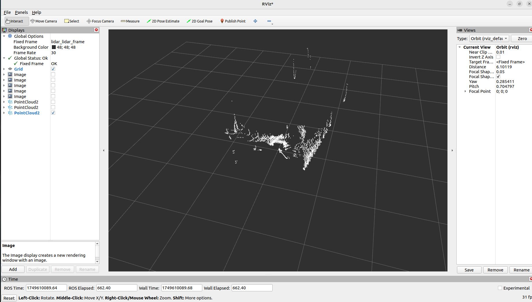
Open RViz.
Add a
PointCloud2orLaserScandisplay.For
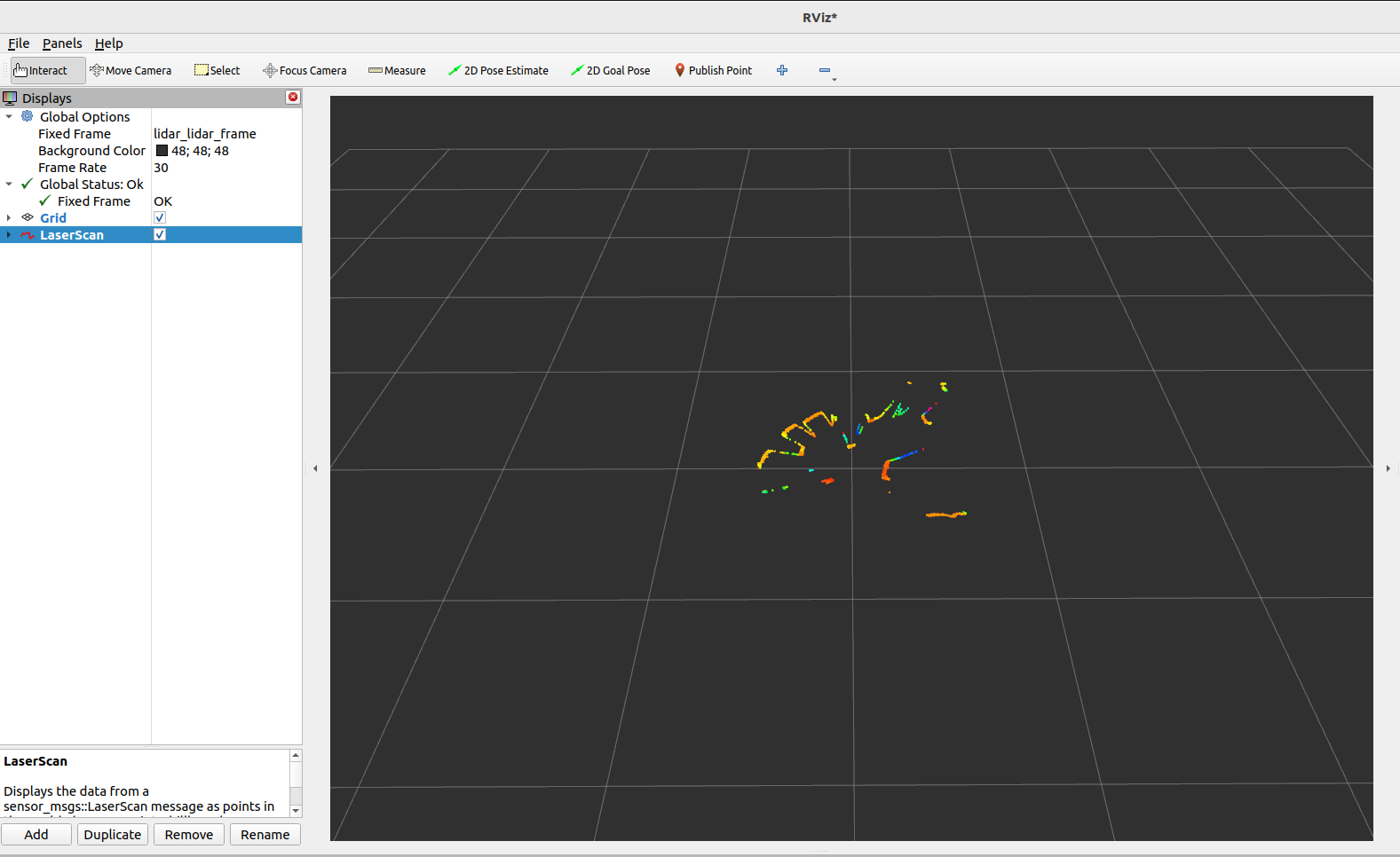
PointCloud2, select the/lidar/cloud/pointstopic; forLaserScan, select the/lidar/scan/pointstopic.Set the
Fixed Frametolidar_lidar_frameto properly align the data.
PointCloud2visualization example:
LaserScanvisualization example:
2. Usage
2.1. Running the Driver
To start the driver, launch the provided ROS1 launch file:
source devel/setup.bash
# Launch the driver with point cloud data
roslaunch orbbec_camera lidar.launch lidar_format:=LIDAR_POINT
# Launch the driver with sphere point cloud data
roslaunch orbbec_camera lidar.launch lidar_format:=LIDAR_SPHERE_POINT
# Launch the driver with laser scan data
roslaunch orbbec_camera lidar.launch lidar_format:=LIDAR_SCAN
# Launch the driver with IMU enabled
roslaunch orbbec_camera lidar.launch enable_imu:=true imu_rate:=50hz
# Launch the driver with both point cloud and IMU data
roslaunch orbbec_camera lidar.launch lidar_format:=LIDAR_POINT enable_imu:=true imu_rate:=100hz
This command will start the node that interfaces with the Orbbec LiDAR device. Please ensure that the LiDAR hardware is properly connected before running this command.
2.2. Get Device Information for Connected LiDARs
rosrun orbbec_camera list_devices_node
This command will list the connected LiDAR devices and display their respective IP addresses and ports. You can use this information to configure the driver to connect to specific devices.
2.3. Check Which Configurations the LiDAR Supports
rosrun orbbec_camera list_camera_profile_mode_node
2.4. 2.4 Parameters and Configuration
The lidar.launch file contains default parameters for the driver. You can customize these settings by modifying the launch file or creating a custom configuration file. Key parameters include:
device_type: Type of device to launch. Options:
lidar,camera. Set tolidarto launch LiDAR device, set tocamerato launch camera device.camera_name: Launch node namespace.
device_num: Number of devices. Must be filled if you need to launch multiple devices.
upgrade_firmware: Firmware upgrade function. Input parameter is firmware path.
connection_delay: Delay time for reopening device (in milliseconds). Immediately reopening device during hot-plug may cause firmware crash.
publish_tf: Enable TF publishing.
tf_publish_rate: TF publishing frequency.
lidar_format: LiDAR data format. Options:
LIDAR_POINT,LIDAR_SPHERE_POINT,LIDAR_SCANlidar_rate: LiDAR scanning rate.
publish_n_pkts: Number of frames to accumulate before publishing merged data. Range: 1-12000. Only effective when lidar format is
LIDAR_POINTorLIDAR_SPHERE_POINT, used to accumulate specified number of frames before publishing merged point cloud data. Default:1enable_scan_to_point: Convert scan data to point cloud data, publish PointCloud2 data type topic.
repetitive_scan_mode: Repetitive scan mode parameter.
filter_level: Filter level parameter.
vertical_fov: Vertical angle parameter.
min_angle: Minimum angle of LiDAR scanning range in degrees (e.g.,
-135.0). Default:-135.0.max_angle: Maximum angle of LiDAR scanning range in degrees (e.g.,
135.0). Default:135.0.min_range: Minimum measurable distance of LiDAR in meters. Default:
0.05.max_range: Maximum measurable distance of LiDAR in meters. Default:
30.0.echo_mode: LiDAR echo mode. Options:
Last Echo,First Echoenumerate_net_device: Enable automatic enumeration of network devices.
net_device_ip: IP address of network device.
net_device_port: Port number of network device.
log_level: SDK log level, default is
none, options aredebug,info,warn,error,fataltime_domain: Device timestamp type. Options:
device,global,systemenable_heartbeat: Enable heartbeat function, default is
false. If set totrue, camera node will send heartbeat signal to firmware; should also be set totrueif hardware logging is needed.enable_imu: Enable IMU (accelerometer + gyroscope) and output unified IMU topic data.
imu_rate: Unified frequency of IMU (accelerometer and gyroscope).
accel_range: Range of accelerometer.
gyro_range: Range of gyroscope.
linear_accel_cov: Linear acceleration covariance value, default is
0.0001.angular_vel_cov: Angular velocity covariance value, default is
0.0001.
3. Point Cloud Data Details
3.1. Point Cloud Format
PointCloud2 (PointXYZITO) point cloud format is as follows:
float32 x               # X axis, unit: meters
float32 y               # Y axis, unit: meters
float32 z               # Z axis, unit: meters
uint8   intensity       # LiDAR intensity
uint8   tag             # LiDAR tag
uint32  offset_time     # Point cloud offset relative to topic time, unit nanoseconds
3.2. Point Cloud Aggregation Functionality
The publish_n_pkts parameter enables point cloud aggregation functionality, which allows the LiDAR to accumulate a specified number of frames before publishing, then merge these frames into a larger point cloud data package for publishing.
3.2.1. Features:
Parameter Range: 1-12000 frames
Applicable Formats: Only effective when lidar format is
LIDAR_POINTorLIDAR_SPHERE_POINTDefault Value: 1 (no aggregation, each frame published individually)
Purpose: Improve point cloud density, suitable for applications requiring denser point cloud data
3.2.2. Usage Examples:
# Aggregate 10 frames before publishing
roslaunch orbbec_camera lidar.launch lidar_format:=LIDAR_POINT publish_n_pkts:=10

# Aggregate 100 frames before publishing
roslaunch orbbec_camera lidar.launch lidar_format:=LIDAR_SPHERE_POINT publish_n_pkts:=100
Note: Increasing the publish_n_pkts value will improve point cloud density but will also increase latency and memory usage. Please adjust according to actual application requirements.
4. IMU Data
4.1. IMU Topics
When IMU is enabled, the following topics will be published:
/lidar/imu/sample: Unified IMU topic containing synchronized accelerometer and gyroscope data insensor_msgs/Imuformat./lidar/lidar_to_imu: Transform relationship from LiDAR coordinate system to IMU coordinate system.
4.2. Using IMU Data
To enable IMU data collection:
# Launch with IMU enabled
roslaunch orbbec_camera lidar.launch enable_imu:=true imu_rate:=50hz

# Check IMU topics
rostopic list | grep imu

# View IMU data
rostopic echo /lidar/imu/sample
IMU data includes:
linear_acceleration: 3D acceleration data (x, y, z), unit: m/s²
angular_velocity: 3D angular velocity data (x, y, z), unit: rad/s
orientation: Quaternion orientation (not provided by hardware, set to zero)